In this project, I present the design, fabrication and testing of an active dual axis closed loop solar tracking sensor. The compactness of the design facilitates its easy mounting and use on any surface or place exposed to solar irradiance. The solar irradiance is detected by an organic photovoltaic cell (OPV) which scans the sky for the maximum power point. The tracker stops operation at night and has provisions for nocturnal return of the panel(s) too. This system is independent with respect to geographical location of the solar panel(s), diurnal, seasonal variations and is scalable. The operation of the system is independent with respect to the initial configuration and the starting conditions. Experimental testing of the set-up agrees with true sun coordinates with satisfactory degree of accuracy. This work can be extended to reduce the scan time of the sensor.
Publication/Citation
S. Meshram, S. Valvi, and N. Raykar, A cost-effective micro-controller based sensor for dual-axis solar tracking. Proceedings of the 14th International Conference on Renewable Energy and Power Quality, Madrid, Spain, 2016. doi.org/10.24084/repqj14.420
Nomenclature
 | Altitude angle, ° |
 | Inclination angle, ° |
 | Surface azimuth angle, ° |
 | Solar azimuth angle, ° |
 | Solar declination angle, ° |
 | Incidence angle, ° |
 | Local latitude, ° |
 | Local hour angle, ° |
| FF | Fill factor |
| PCE | Power conversion efficiency |
 | Open circuit voltage, V |
 | Short circuit current, A |
| OPV | Organic photovoltaic |
| LDR | Light dependent resistor |
| CCD | Charge-coupled device |
| IDE | Integrated development environment |
| MPP | Maximum power point |
Introduction/Literature Survey
Energy is one of the primary factors affecting the socio-economic development of any nation. About 82% of the total energy consumption of the world comes from fossil fuels [1, 2]. Solar energy harvesting is becoming increasingly important as the cost and environmental impact of our non-renewable energy sources has become apparent. Solar radiation is one of the most important renewable sources of energy (others include waterpower, wind, biomass and geothermal energy). The source of solar radiation are ongoing nuclear fusion reactions in the sun’s core and is practically inexhaustible, since the sun has a predicted life span of 5 billion more years [3]. The annual energy input of solar irradiation on the earth (5% Ultraviolet, 43% Visible and 52% Infrared) exceeds the world’s yearly consumption by several thousand times [4]. Also, photovoltaic (PV) cells are one of the most promising devices to convert solar energy into electricity.
As a result, solar photovoltaic systems have been in development since late 1800s when Charles Fritts built a 30 cm2 cell from Selenium and Gold (1883) [5]. In, 1954, Chaplin et al demonstrated solar cells based on P-N junctions with an efficiency of 5-6 %. Recent research has reported a peak efficiency of around 46.0% under standard testing conditions [1000 W/m2 solar intensity, 25 °C ambient temperature and an air mass of 1.5 (ASTM G-173-03) ] [6] with an average efficiency of around 10-25%.
The power output of a given photovoltaic cell depends on operating temperature, irradiance and incident angle of solar radiation [7]. Not much control can be achieved on the first two parameters for a given cell as they are primarily dependent on the geographical location. On the other hand, the output of PV cell can be substantially increased by a solar tracker, which always makes sunlight to be incident normally (perpendicularly) to the PV cell. Although not essential it can boost the collected energy by 10-100% in different periods of day time and geographical locations [8]. Another study reports that single axis trackers improve efficiency by up to 40% [9]. Also, tests have shown that dual axis trackers improves efficiency by almost 50% (35 to 42% by East-West trackers and 5 to 8% by North-South) [10].
An ideal solar tracker should compensate for both, changes in altitude (during seasonal changes) and azimuth angle of the sun; as pointed out by Clifford et al [6]. Additionally, there must be a provision of nocturnal return of the solar panel to align with the sunrise reducing energy losses in the early hours of sunshine.
Initial works in solar tracking were presented by Zerlaut et al [11] and Haywood et al [12] in the year 1976. More recent works employ hybrid tracking strategies employing algorithms to suit different illumination and geographical conditions as can be seen in [13, 14]. Tracking accuracy as high as 0.1° can be obtained through picture processing techniques as can be seen in [15]. A new approach based on computer vision, low cost hardware and deep learning can be found in [16].
Poulek et al. designed a single axis solar tracker based on an arrangement of solar cells connected directly to a reversible DC motor. In their work, solar cells, both sense and provide energy for tracking. Sensing/driving solar cells are balanced to each other and differential signal is used to overcome friction and aerodynamic drag. The area of the auxiliary solar panel of the tracker is about 2% of the area of the moved solar collectors; while collectable energy surplus is up to 40%. With slight modifications, this system can be used for space panel tracking in addition to terrestrial applications but requires a set of bifacial solar cells per panel to be tracked [17, 18].
Roth et al. designed and constructed a two-axis (one axis from east to west and the other for elevation) sun following device with the use of a pyrheliometer as a measuring instrument. The device works in two modes viz. clock mode and sun mode. In the clock mode, the tracker computes the position of the sun based on the date/time information in its internal clock. Panel position errors are measured during the day and stored for later analysis. The data gathered during the day are analyzed, and a new improved set of parameters for the installation errors is computed. This data is used the next day to compute more accurate positions of the sun. In the sun mode, the tracker uses data of the sun position to control the panel position. If the intensity drops below a certain level, it falls temporarily back to the clock mode [14,19].
Rizk et al. designed a solar tracker employing a new principle of using small solar cells to function as self-adjusting light sensors, providing a variable indication of their relative angle to the sun by detecting their voltage output. A power increase of 30% was obtained by using this strategy [20].
Based on their functioning principle, Sun trackers can be classified into three types: passive, microprocessor based and electro-optically controlled units [21].
Passive trackers rely on the differential expansion of substances exposed to different amount of irradiance. They are based on thermo-sensitive substances that adjust the position of the receiving panel in accordance with the position of the sun. Freon and bimetallic strips are commonly used substances. These systems are simple, without any electronic controls or motors. Some of the drawbacks of this system are possible involvement of poisonous substances, slow response and absence of a nocturnal return mechanism. A novel passive tracker can be found in [7]; some other interesting passive tracker designs can be found in [22-24].
Microprocessor based trackers rely on calculations of the Sun’s position through mathematical relations such as


The latest types of trackers are those which use both microprocessors and electro-optic sensors (LDRs and CCDs) for their operation [10-12, 17-19, 25-34].
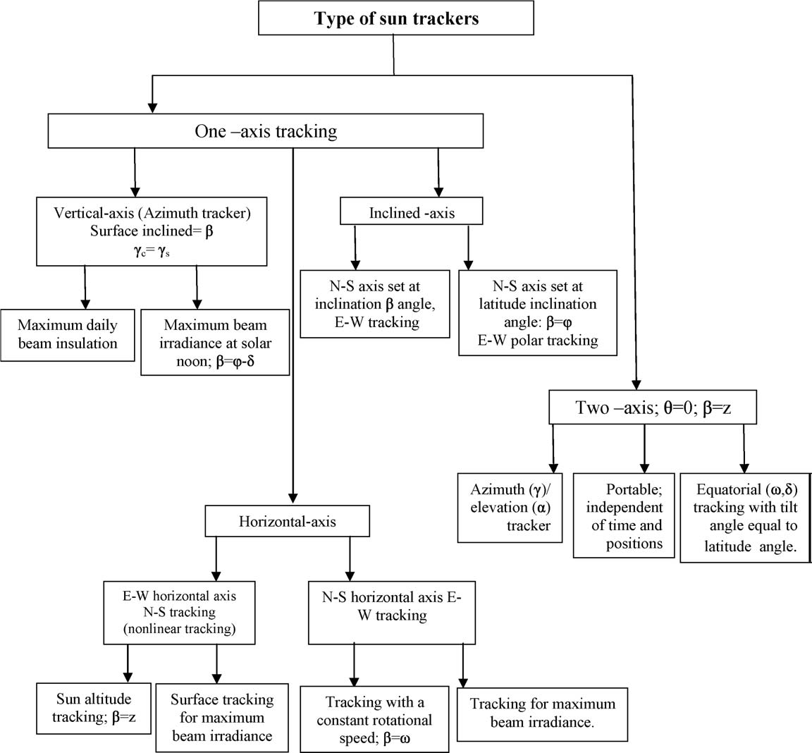
A more generic classification classifies them as one-axis and two-axis devices as illustrated in figure above. A detailed account of different solar tracking systems can be found in reviews [8, 35].
In this article, a novel optoelectronic closed-loop dual-axis solar tracking sensor is designed with the help of an OPV cell which can be readily implemented in a wide range of sun tracking scenarios. The design especially suits use in developing and under-developed countries having limited access to technology. A prototype sensor was constructed and evaluated for various performance parameters. Subsequent sections of this article describe the objectives of the study, solar tracking system description in detail, algorithm used followed by experimental results of testing. Concluding remarks are presented at the end of the article.
Solar Tracker Sensor Description
The sensor is broadly divided into mechanical and electrical components, which are combined to form the solar tracking system. The mechanical structure comprises of the frame, whereas the electrical system consists of the motors, OPV cell and microcontroller. The block diagram shown in figure below gives an operational overview of various components used.
The construction of the solar sensor is shown in figure below. The setup consists of two servo motors (b) and (c), one of which (b) is mounted on the frame (a) to facilitate East-West movement of the organic photovoltaic (OPV) cell (d). The cell acts as a primary sensing device for the tracker. A servo motor (c) is mounted at the base which facilitates the North-South movement of the OPV cell. The cell is connected to the fork shaped frame (a) such that it can rotate about the horizontal axis when moved by the servo (b) and vertical axis when moved by the servo (c). The tracking algorithm of the sensor is controlled by a microcontroller (e).
Mechanical Structure
The solar tracking sensor weighs around 200 g and has overall dimension of 200 × 200 × 200 mm. The compactness of the system enables it to be mounted conveniently with minimal use of space. The prototype was fabricated from acrylic sheets of 3 mm thickness which are bonded by a general-purpose adhesive. The frame is designed such that free 180° and 360° rotational movement of the OPV cell (120 × 80 mm) is allowed with respect to both horizontal and vertical axis respectively when operated by the servo motors. The tracking sensor is designed to pinpoint both the azimuth and elevation angles. Figure below shows the actual working model (prototype) of the sensor constructed using above mentioned materials.
Electrical System
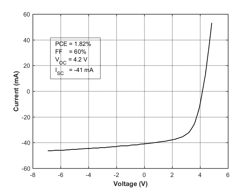
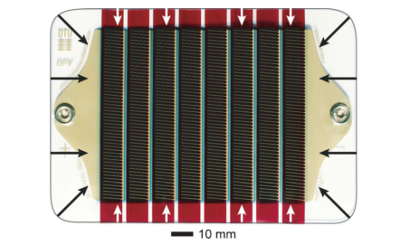
Abundance, fast manufacture, and low cost are what ideally epitomize organic and polymer photovoltaics and is therefore a choice of sensor in this tracking device. These cells are indium-tin oxide (ITO) free and have been shown to exceed 10 000 hours of lifetime under standard outdoor exposure conditions. The normal operation temperature range is from – 80 °C to 120 °C and the sensor used in the prototype weighs around 5 g. The I-V response of the OPV cell and an actual photograph of the cell used in the prototype is shown in the figure below [36].
The driving mechanism of the OPV for executing its tracking cycle includes two servo motors. A smaller servo (TowerPro SG90) is used to rotate the sensor in East-West tracking while a bigger motor (Futaba S3003) is used to turn the fork frame. PWM (Pulse Width Modulation) is used to drive the servo motor at a controlled speed correspond to a maximum voltage of 6 V. The duration or width of the pulse determines the angle of the shaft’s rotation.
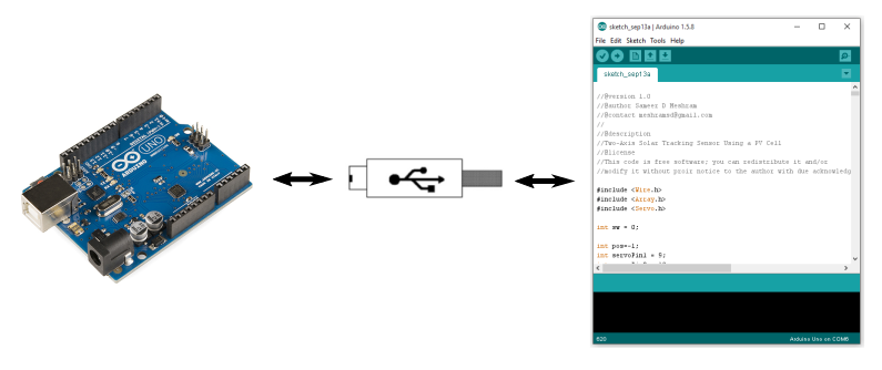
An open source microcontroller board Arduino Uno (shown below) was used as a primary controller for the servo motors and to analyze the OPV cell output. The Uno is a microcontroller board based on the ATmega328P. The analog voltage provided by the OPV cell is converted into digital signal for processing. As the input-output pins of the microcontroller can only operate between 0-5 V, a simple voltage divider circuit was constructed to input the voltage from the cell (0 to 10 V) to the microcontroller. The Arduino IDE is used to program the microcontroller. The C/C++ program can be written and compiled in the IDE before uploading into the Arduino Uno board.
The power required to drive the two servo motors and the microcontroller was taken from a USB port of a PC. It can also be taken from the solar energy produced by the panels to which the sensor caters or any other external direct voltage source.
Algorithm
The sensor first scans for local Maximum Power Point (MPP) in the horizon i.e. rotating the OPV cell about the vertical axis (figure below) and sets at azimuth angle corresponding to the local MPP. The local MPP is calculated at the highest magnitude of voltage across the cell for any given scan.
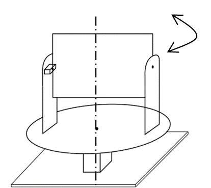
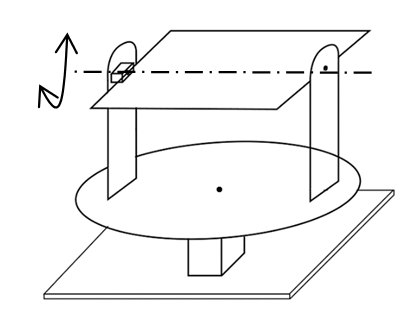
Similarly, it scans for local MPP in the East-West direction rotating the OPV cell about the horizontal axis (figure below) and sets at altitude angle corresponding to the local MPP.
Next, the global (overall) MPP is obtained by taking into consideration both the local East-West and North-South MPPs. Once the final position of the sensor corresponding to global MPP is calculated; the sensor sets the panels it is connected to at the calculated positions till the next scan or search cycle begins. Each scan cycle is of around 20 second duration which is performed at an interval of 30 minutes. It should be noted that while the duration of a scan remains constant at 20 seconds, the user has total control over the interval of scan.
Performance Testing and Experimental Results
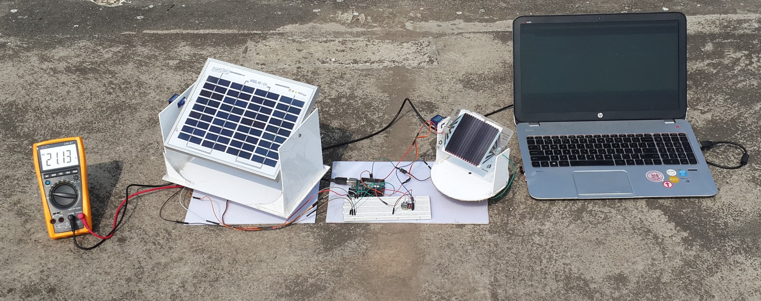
In order to validate the accuracy for the sensor it was necessary to compare the experimental results with that obtained through mathematical formulae for altitude, azimuth angles and the Sun position/angle calculators [37, 38]. To obtain this data, tests were conducted with the setup as shown in figure below during quarter 1 of 2016. Tests were made at latitude 18.9803578, longitude: 72.8148362, and at an altitude of 52 meters above sea level with average temperature of 34 °C at Mahalaxmi-Mumbai, India.
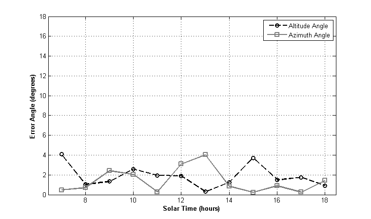
Tracking accuracy of the sensor throughout the day was determined in terms of azimuth and altitude angles and was plotted against solar time (figures below). A comparative analysis of true and observed values versus solar time showed a maximum deviation of ± 4°. The sensor output was also fed to a test panel to visually validate tracking.


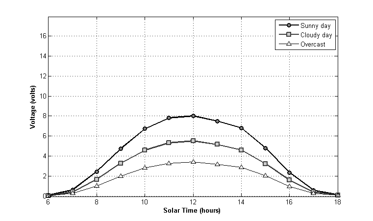
Moreover, sensor was tested under three different illumination conditions – a sunny day, a cloudy day and an overcast day to establish performance consistency in different climatic condition (figure below). No variation was observed in location of the MPP under these conditions due to the relative nature of the algorithm.
Conclusion
The proposed solar tracker design was demonstrated to be a low cost (~$ 30), simple to construct, use and maintain. This system was designed with a view that it can be fabricated, assembled and be made operational by anyone with very basic understanding of electrical circuits. It also employed commonly available materials and easy fabrication techniques. The sensor implemented an organic photovoltaic cell which is Indium Tin Oxide (ITO) free and is environmentally friendly as compared to few of its Silicon counterparts. With a large tracking angle, it can be deployed in any geographical location, including regions above polar circle (Russia, Canada, Alaska, Scandinavia, etc.) Experiments conducted showed maximum deviation of ± 4° from true values of observed azimuth and altitude angles. In addition, the system was found to be independent of the illumination conditions due to the relative nature of the algorithm.
Future work for the study may include testing a production intent set-up for its durability and reliability when subjected to various environmental conditions, reducing the scan cycle time, performing life cycle assessment (LCA) and life cycle cost assessment (LCC).
Acknowledgement
The author acknowledges reception of free OPV cell sample from Technical University of Denmark (DTU) and the funding and support provided by Sardar Patel College of Engineering (SPCE), Mumbai in fulfilment of this work.
C++ Sample Code
//@version 1.0
//@author Sameer D Meshram
//@contact meshramsd@gmail.com/meshrams@uw.edu
//ver 1.0 2016 ver 1.1 2019
//@description
//Two-Axis Solar Tracking Sensor Using a PV Cell
//@license
//This code is free software; you can redistribute it and/or
//modify it without proir notice to the author with due acknowledgement.

#include <Wire.h>
#include <Array.h>
#include <Servo.h>

int sw = 0;

int pos=-1;
int servoPin1 = 9;
int servoPin2 = 10;

Servo servo1;
Servo servo2;

int a1,b1,a2,b2,a3,b3,a4,b4,a5,b5,a6,b6,a7,b7,a8,b8,a9,b9,a10,b10,a11,b11;
int a12,b12,a13,b13,a14,b14,a15,b15,a16,b16,a17,b17,a18,b18,a19,b19;
int a20,a21,a22,a23,a24,a25,a26,a27,a28,a29,a30,a31,a32,a33,a34,a35,a36,a37;

void setup()
{
	servo1.attach(servoPin1);
	servo2.attach(servoPin2);
	Serial.begin(9600);
	pinMode(2, INPUT);
}

void loop()
{
	int sw = 0;
	sw = analogRead(A0);
	while(analogRead(A0)==LOW)//To execute loop on the trigger of a push button
	{
//=======================================================================//
// For Servo 2 (Mounted at Base)										 //
//=======================================================================//
	servo1.write(0);
	servo2.write(0);

	delay(500);

	float SolarValueb1 = analogRead(A1);
	float SolarVoltageb1 = SolarValueb1 * (5.0/1023.0);
	b1 = Serial.print(SolarVoltageb1);
	Serial.print("\t");
	Serial.println(0);
	delay(900);

	int j = 2

	for (int i = 5; i <= 90; i = i+5)
	{
		if (j < 20)
		{
			servo2.write(i);
			float SolarValueb[j] = analogRead(A1);
			float SolarVoltageb[j] = SolarValueb[j]*(5.0/1023.0);
			b[j] = Serial.print(SolarVoltageb[j]);
			Serial.print("\t");
			Serial.println(i);
			delay(450);
			j = j+1;
		}

	}

	float Array2[19] = {SolarVoltageb1,SolarVoltageb2,SolarVoltageb3,SolarVoltageb4,
	SolarVoltageb5,SolarVoltageb6,SolarVoltageb7,SolarVoltageb8,
	SolarVoltageb9,SolarVoltageb10,SolarVoltageb11,SolarVoltageb12,
	SolarVoltageb13,SolarVoltageb14,SolarVoltageb15,SolarVoltageb16,
	SolarVoltageb17,SolarVoltageb18,SolarVoltageb19};

// Maximum Value of Array reference:https://processing.org/discourse/beta/num_1133369707.html , John G, 3Oth November 2005.

	float maxValueb=0;
	int posb=-1;
	for(int i=0;i<38;i++)//For checking all the values of the array
		{
		if(Array2[i]>maxValueb)//To see if the present value is the highest
			{
			posb=i;
			maxValueb=Array2[i];
			}
		}

	Serial.print("Maximum Voltage ");//Printing values in the serial monitor
	Serial.print(maxValueb);
	Serial.print(" At ");
	Serial.print(posb*5);
	Serial.println(" degrees in Horizontal Plane");
	servo2.write(posb*5);//Set servo 2 at a desired position according to the voltage obtained

//Complete code available on request
}
References
[1] “Key World Energy Statistics 2014,” [Online] Available: http://www.iea.org/statistics/ [Accessed 19-Sept-2018].
[2] “Electricity Net Generation: Total (All Sectors),” [Online]Available:http://www.eia.gov/totalenergy/data/monthly/pdf/sec7_5.pdf [Accessed 19-Sept-2018].
[3] S. Lawrence, “Some Interesting Facts about the Sun.” [Online]. Available:http://www-istp.gsfc.nasa.gov/istp/outreach/workshop/thompson/facts.html. [Accessed: 19-Sept-2018].
[4] D. Wohrle and D. Meissner, “Organic Solar Cells,” Adv. Mater., vol. 3, no. 3, pp. 129–138, Mar. 1991.
[5] Luque A, Hegedus S. Handbook of photovoltaic science and engineering. Hoboken (NJ): Wiley; 2003.
[6] Green MA, Hishikawa Y, Warta W, et al. Solar cell efficiency tables (version 50). Prog Photovolt Res Appl. 2017;25:668–676. https://doi.org/10.1002/pip.2909.
[7] M. J. Clifford and D. Eastwood, “Design of a novel passive solar tracker,” Sol. Energy, vol. 77, no. 3, pp. 269–280, Sep. 2004.
[8] H. Mousazadeh, A. Keyhani, A. Javadi, H. Mobli, K. Abrinia, and A. Sharifi, “A review of principle and sun-tracking methods for maximizing solar systems output,” Renew. Sustain. Energy Rev., vol. 13, no. 8, pp. 1800–1818, Oct. 2009.
[9] E. Lorenzo, M. Pérez, A. Ezpeleta, and J. Acedo, “Design of tracking photovoltaic systems with a single vertical axis,” Prog. Photovoltaics Res. Appl., vol. 10, no. 8, pp. 533–543, 2002.
[10] A. Argeseanu, E. Ritchie, and K. Leban, “New low cost structure for dual axis mount solar tracking system using adaptive solar sensor,” in 2010 12th International Conference on Optimization of Electrical and Electronic Equipment, 2010, pp. 1109–1114.
[11] Zerlaut, Gene A., and Robert F. Heiskell. “Solar tracking device.” U.S. Patent No. 4,031,385. 21 Jun. 1977.
[12] Haywood, George Lewis, and Wesley Joseph Haywood. “Solar collector and drive circuitry control means.” U.S. Patent No. 4,082,947. 4 Apr. 1978.
[13] F. R. Rubio, M. G. Ortega, F. Gordillo, and M. López-Martínez, “Application of new control strategy for sun tracking,” Energy Convers. Manag., vol. 48, no. 7, pp. 2174–2184, Jul. 2007.
[14] P. Roth, a. Georgiev, and H. Boudinov, “Cheap two axis sun following device,” Energy Convers. Manag., vol. 46, no. 7–8, pp. 1179–1192, 2005.
[15] G. P. A. Minor M. Arturo, “High–Precision Solar Tracking System,” 2010. [Online]. Available: http://www.iaeng.org/publication/WCE2010/WCE2010_pp844-846.pdf. [Accessed: 19-Sept-2018].
[16] J.A. Carballo, et al., New approach for solar tracking systems based on computer vision, low cost hardware and deep learning, Renewable Energy (2018), https://doi.org/10.1016/j.renene.2018.08.101.
[17] V. Poulek and M. Libra, “A very simple solar tracker for space and terrestrial applications,” Sol. Energy Mater. Sol. Cells, vol. 60, no. 2, pp. 99–103, Jan. 2000.
[18] V. Poulek and M. Libra, “New solar tracker,” Sol. Energy Mater. Sol. Cells, vol. 51, no. 2, pp. 113–120, Feb. 1998.
[19] P. Roth, A. Georgiev, and H. Boudinov, “Design and construction of a system for sun-tracking,” Renew. Energy, vol. 29, no. 3, pp. 393–402, 2004.
[20] J. Rizk and Y. Chaiko, “Solar Tracking System: More Efficient Use of Solar Panels,” World Acad. Sci. Eng. Technol., vol. 41, pp. 313–315, 2008.
[21] H. Bentaher, H. Kaich, N. Ayadi, M. Ben Hmouda, A. Maalej, and U. Lemmer, “A simple tracking system to monitor solar PV panels,” Energy Convers. Manag., vol. 78, pp. 872–875, 2014.
[22] Zomeworks Corporation, Passive solar TRACK RACK, Albuquerque, NM, US Pat. No. 4275712.
[23] Berger, Alexander. “Sun tracker system for a solar assembly.” U.S. Patent No. 5,798,517. 25 Aug. 1998.
[24] M. Comsit and I. Visa, “Design of the linkages type tracking mechanisms of the solar energy conversion systems by using Multi Body Systems Method Transilvania University of Brasov Transilvania University of Brasov,” in 12th IFToMM World Congress, Besançon (France), 2007, no. 12, pp. 1–6.
[25] C. Alippi and C. Galperti, “An Adaptive System for Optimal Solar Energy Harvesting in Wireless Sensor Network Nodes,” IEEE Trans. Circuits Syst. I Regul. Pap., vol. 55, no. 6, pp. 1742–1750, Jul. 2008.
[26] A. Al-Mohamad, “Efficiency improvements of photo-voltaic panels using a Sun-tracking system,” Appl. Energy, vol. 79, no. 3, pp. 345–354, 2004.
[27] H. Arbab, B. Jazi, and M. Rezagholizadeh, “A computer tracking system of solar dish with two-axis degree freedoms based on picture processing of bar shadow,” Renew. Energy, vol. 34, no. 4, pp. 1114–1118, 2009.
[28] J. Beltran A., J. L. Gonzalez Rubio S., and C. D. Garcia-Beltran, “Design, Manufacturing and Performance Test of a Solar Tracker Made by a Embedded Control,” in Electronics, Robotics and Automotive Mechanics Conference (CERMA 2007), 2007, pp. 129–134.
[29] C. S. Chin, A. Babu, and W. McBride, “Design, modeling and testing of a standalone single axis active solar tracker using MATLAB/Simulink,” Renew. Energy, vol. 36, no. 11, pp. 3075–3090, Nov. 2011.
[30] P. K. Das, M. A. Habib, and M. Mynuddin, “Microcontroller Based Automatic Solar Tracking System with Mirror Booster,” vol. 4, no. 4, pp. 125–136, 2015.
[31] N. Dasgupta, A. Pandey, and A. Mukerjee, “Voltage-sensing-based photovoltaic MPPT with improved tracking and drift avoidance capabilities,” Sol. Energy Mater. Sol. Cells, vol. 92, no. 12, pp. 1552–1558, Dec. 2008.
[32] A. Kassem and M. Hamad, “A microcontroller-based multi-function solar tracking system,” in 2011 IEEE International Systems Conference, 2011, pp. 13–16.
[33] M. T. A. Khan, S. M. S. Tanzil, R. Rahman, and S. M. S. Alam, “Design and construction of an automatic solar tracking system,” in International Conference on Electrical & Computer Engineering (ICECE 2010), 2010, pp. 326–329.
[34] Yazidi, F. Betin, G. Notton, and G. Capolino, “Low cost two-axis solar tracker with high precision positioning,” 2006 1st Int. Symp. Environ. Identities Mediterr. Area, ISEIM, pp. 211–216, 2006.
[35] H. J. Loschi, Y. Iano, J. León, A. Moretti, F. D. Conte, and H. Braga, “A Review on Photovoltaic Systems: Mechanisms and Methods for Irradiation Tracking and Prediction,” Smart Grid Renew. Energy, vol. 06, no. 07, pp. 187–208, 2015.
[36] F. C. Krebs, M. Hösel, M. Corazza, B. Roth, M. V. Madsen, S. A. Gevorgyan, R. R. Søndergaard, D. Karg, and M. Jørgensen, “Freely available OPV-The fast way to progress,” Energy Technol., vol. 1, no. 7, pp. 378–381, 2013.
[37] “Sun Position Calculator”, [Online], Available: https://pveducation.org/pvcdrom/properties-of-sunlight/sun-position-calculator. [Accessed: 19-Sept-2018].
[38] “Sun Earth Tools”, [Online], Available: https://www.sunearthtools.com/dp/tools/pos_sun.php [Accessed: 19-Sept-2015].
