Introduction
A crane is a machine which can raise, lower and maneuver objects from one place to another. An overhead crane consists of the following three primary motions: 1. Motion of the hoist (vertical travel), which raises and lowers the load. 2. Motion of the trolley (cross travel) – which allows the hoist to be positioned above the load and 3. The gantry or bridge motion (long travel) – which allows the crane to cover the working area.
Though this project involved the design of several EOT crane components and assemblies. This article highlights the design/selection of only three components – box girders, rope and snatch block.
Types of Electric Overhead Cranes
There are a great variety of highly specialized cranes that can be made to suit particular application(s); however the majority can be classified under one of following categories.
- Single Girder Cranes – This type consists of a single bridge girder supported on two end trucks.
- Double Girder Cranes – This type consists of two bridge girders supported on two end trucks.
- Gantry Cranes – The distinction of Gantry cranes from other types is that it is rigidly supported on two or more legs running on fixed rails or runways.
- Monorail – These cranes generally consist of a hoist supported by a single I beam with long travel motion of the bridge.
Common Terms and Components

- Bridge / Girder – It is one of the principal structural components of an overhead crane which spans the width of the building. The bridge carries the hoist which travels along the length of the girders during operation.
- Duty or Service Class / Group – are a set of service classifications based on the frequency of use and percentage of lifts at or some fraction of rated capacity.
- End Trucks – These are located on either side of the bridge and consist of the assembly on which the entire crane travels. The assembly consisting of structural members, wheels, bearings, axles, electric drive motors, etc.
- Rated Capacity (RC) or Safe Working Load (SWL) – The rated capacity is the maximum working load that can be lifted by a crane usually expressed in tons. Note: The terminology – Safe Working Load is now obsolete for legal implications.
- Runway – The track on which runway rails are mounted. They are usually a part of the building structure.
- Runway Rails – These are rail beams on the girders upon which the crane trolley travels.
- Hoist – The hoist is responsible to raise, hold and lower the maximum rated load. It consists of motor drive, coupling, brakes, gearboxes, rope drum, etc.
- Trolley or Crab – It is the cross-travel unit which accommodates the hoist from which the lifting hook is lowered and raised. The trolley also facilitates lateral movement on the runway rails.
- Bumper – it is an energy absorbing mechanism or device intended for reducing the impact of a moving crane or trolley when it hits the stops.
- Long Travel – This is the motion of the bridge or girder(s) on the runway.
- Cross Travel – This is the motion of the trolley or crab along the bridge/girder.
- Hook Height – This is the distance from the datum to the highest position of the hook.
Problem Statement
You are the chief design engineer for a reputed manufacturer of material handling equipment including EOT cranes. Your company has received an important enquiry/supply of an EOT crane as per the following technical specification summary.
Rated capacity (RC) or hook load ( ) ) | 7 metric ton (68,670 N) |
| Duty or service class | ISO M7 equivalent to CMMA E [1] |
| Span of crane | 24 ± 0.2 |
| Longitudinal travel of crane | 70 ± 0.5 |
Main hoist speed ( ) ) | 3.0 m/minute |
| Long travel speed | 20.0 m/minute |
| Cross travel speed | 16.0 m/minute |
Other Notation and Assumptions
Loads due to the dead weight of the mechanism or component & dead weight of those parts ( ) ) | 5% of Rated capacity (RC) = 3434 N |
Dynamic loading arising from the acceleration or braking of the motion & from skewing interaction between the crane & track ( ) ) | *Refer calculation below |
| Braking time (t) | 2 seconds |
Number of falls ( ) ) | 4 |
| Load carrying efficiency of each fall (n) | 94% |
Impact factor for hook direct or indirect loads ( ) ) | 1.50 [2] |
Stress factor based on duty or service class ( ) ) | 2.0 [2] |
Safety factor depending on the material used ( ) ) | 1.00 [2] |
Duty factor ( ) ) | 1.90 [2] |
| Stress factor corresponding to the loading case () | 3.15 [2] |
Factor dependent on construction of wire rope for sheave sizing ( ) ) | 1.0 for 6 × 36 ropes [2] |
Coefficient dependent on type of receiving system for sheave i.e. number of pulleys & reverse bends ( ) ) | 1.12 [2] |
Calculations
Although this project consisted of design and selection of several EOT crane components. Here we will show the calculations for – rope, snatch block and girders only.
Rope Selection


Taking wire rope factor of safety (


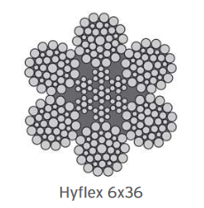
Rope selected is Usha Martin HYFLEX 6X36, Nominal Diameter 18 mm, Rope Grade 1770 N/mm2For rope selection using table in catalogue [4] as shown below.

Sheave Sizing

Based on the design standard, taking duty factor (C_df) = 1.9, factor dependent on construction of wire rope (C_rc) = 1.0, and coefficient dependent upon the type of receiving system i.e. number of pulleys and reverse bends (Cπ) = 1.12 [2].

Rounding off to nearest standard diameter, implies final sheave diameter of 500 mm.
Sheave Pin Sizing


Using equation in IS 3177 for permissible stress and taking ultimate tensile strength of E650 steel as per IS 2062:2011 [5]


Considering that the pin is under double shear and using a factor of √3 to divide the ultimate permissible stress to shear permissible stress.


Checking performance in bending, assuming simply supported with two-point load configuration as shown below. Figure from reference [6].
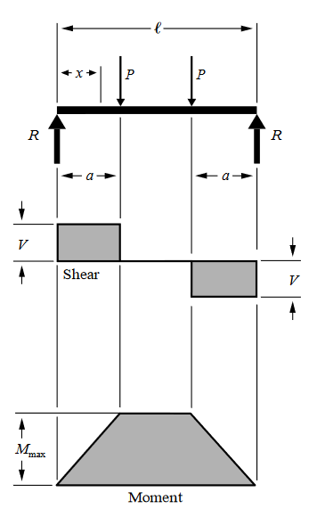


Stress at d = 30 mm is 672.28 MPa (above permissible limit), Stress at d = 55 mm is 109.10 MPa. Therefore, using the value of sheave pin diameter d = 55 mm.
Bearing Selection for Sheave and Pin
Calculating the mean radial load based on equations given in [7-9] and assuming the load is evenly divided between two pulleys (since four falls of rope).


Calculating the basic rating life for the bearing with a statistical reliability of 90% also known as the L_10 life. We will use a cylindrical roller bearing (K is 10/3) as there are no axial loads and expect it to last 3000 hours at 50 rpm [10].


Selecting SKF bearing NJ 311 ECJ based on C value and calculated pin diameter.
Hook Selection


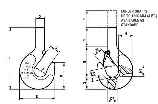
Selecting CM Works RSN8 12.5 Long metric ton carbon alloy hook form [11]
| Size (mm) | D | F | L | X | P | J | Y | H | R | G |
| RSN 8 Carbon Steel (12.5 metric ton) | 271 | 100 | 713 | 67 | 208 | 80 | 350 | 112 | 268 | 95 |
Nut for Hook

Doing an iterative calculation and using values for M68 Class 8 DIN 934 from reference [12] and [13]

For Class 8 the ultimate tensile strength is 1000 MPa [13], Using equation for allowable stress from design standard [2].


Selection of Thrust Bearing for Hook
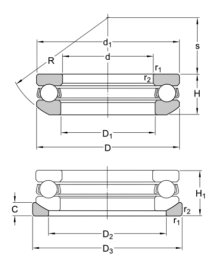
We have a total design hook load of approximately 11 tons or 107 kN. Using SKF bearing calculator [15] to select appropriate bearing based on the selected hook dimensions. Here we select SKF thrust bearing with 53314 U 314 with dimensions as shown below.
| Size (mm) |  |  |  |  |  |  |  |  |  |  |  |  |
| SKF 53314U 314 | 70 | 125 | 44.2 | 48 | ≈ 125 | ≈ 72 | 98 | 130 | 13 | 100 | 43 | 1.1 |
Cross Block Sizing
Assuming that the cross block is in bending similar to a simply supported beam. The maximum bending moment for the beam is given by 


Since we have too many unknowns, we will assume the initial size of the cross block to be 175 × 175 mm. Therefore, effective b can be taken as b = 175 – 70 (subtracting nominal hook and bearing cross section).


But since size of pin diameter is 55 mm, we will have to consider the shear that might take place in determining overall height.


We will change this value to 85 mm to add margin of safety in addition above what is accounted for permissible shear stress.
Design of Side Plates
Nominal width of side plates = 500 mm (same as diameter of sheave). Height of plate = 1000 mm (end to end) based on CAD assembly considering clearances. For thickness of plate, we will be considering shear through pins.


Also, considering bearing allowable. Bearing area for hole in side plate 

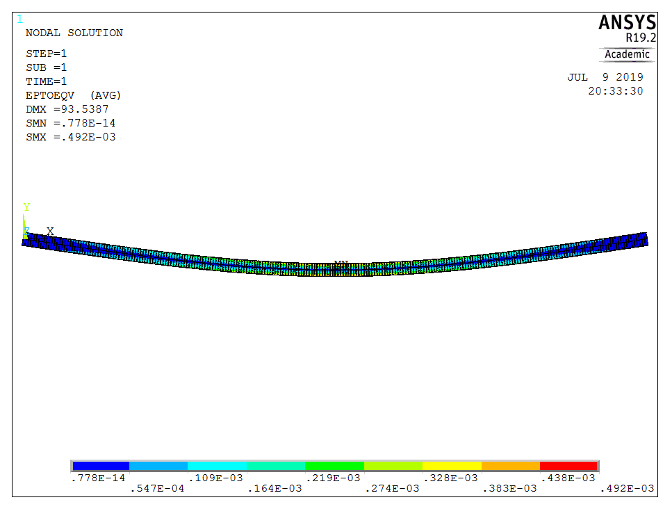
Gives t = 4.74 mm, making this value 5 mm to add margin of safety. Now, we also must check for stress concentration effects in the side plates. Using Ansys static structural to perform analysis as is shown below.
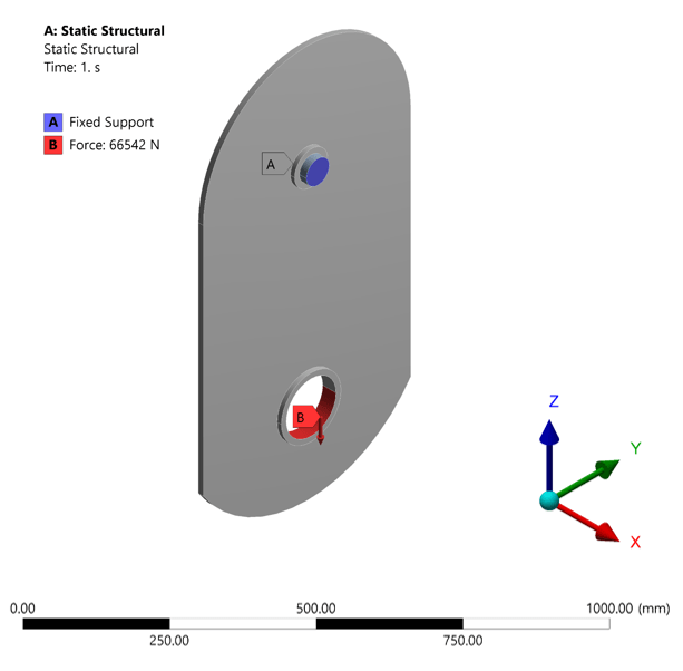
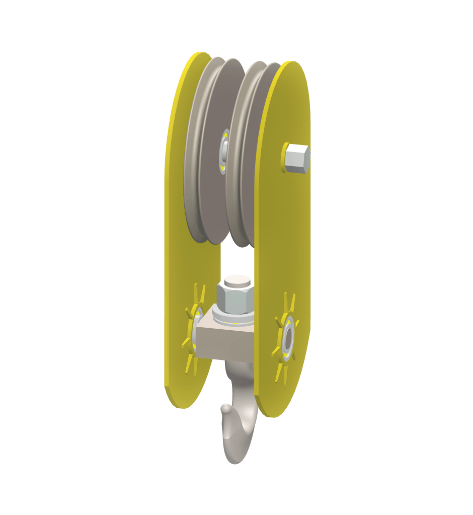
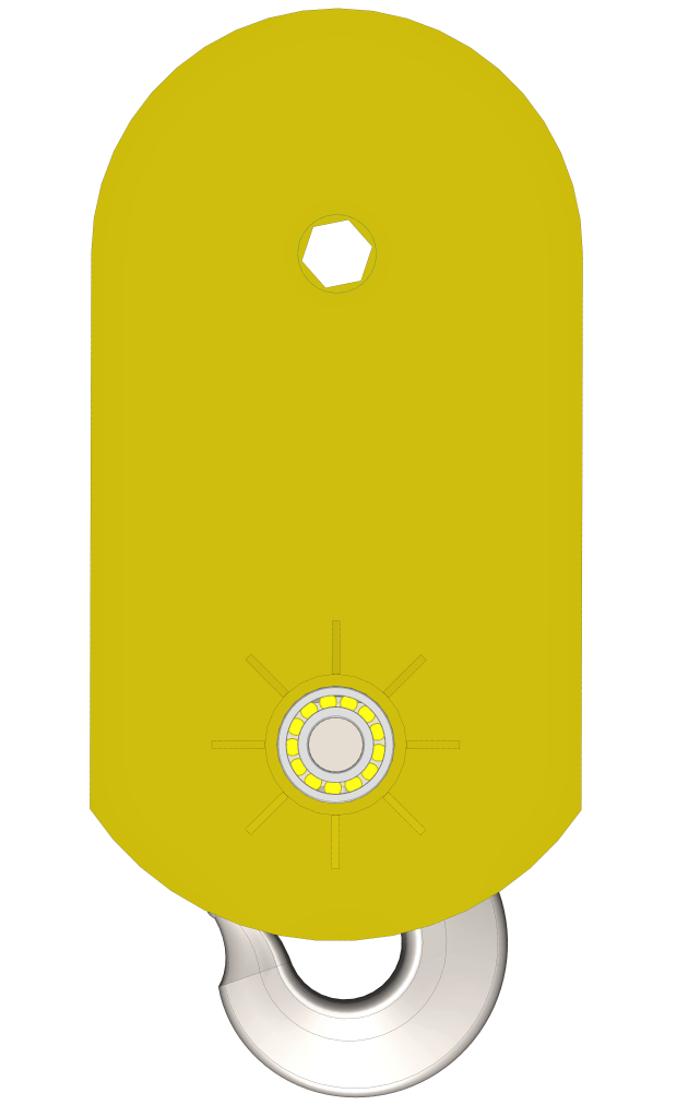
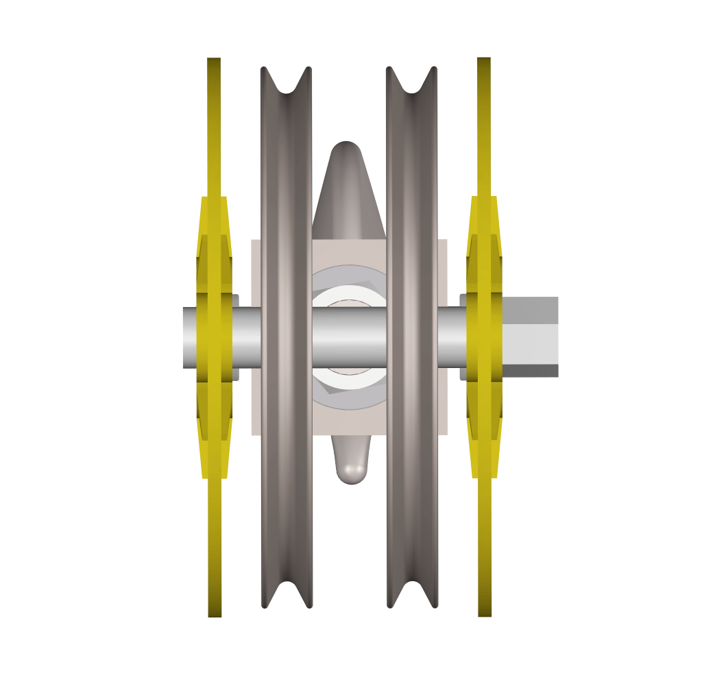
The final thickness of side plates is kept at 12 mm with 12 mm thickness sleeves. CAD assembly of the snatch block based on the calculations above is shown below.
Box Girder Sizing
To size the box girder, we assume it as a simply supported beam with concentrated load at the center (most critical condition). Ours is a double girder crane with longitudinal span of 24 meters and theoretical load of 106439 Newton. We will design the girders for 25% more than the theoretical load i.e. 133048 N. Also, since this load is divided between two girders, each must take a load of 66524 Newton.
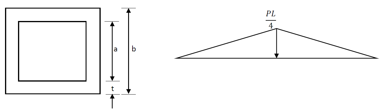
Maximum moment for beam configuration as shown in the figure above


The yield stress for box girder conforming to ASTM A500 Grade B from reference [16] is 315 MPa, keeping a factor of safety of 2. The permissible stress can be calculated as:

Therefore, maximum stress (at farthest position from neutral axis)


In case we choose a 20 x 20 in (508 x 508 mm) box girder from [16], the wall thickness should be


Since the above deflection is acceptable. Recalculating the stress for new dimensions.

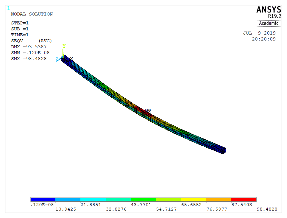
Comparing hand calculation results with finite element analysis using Beam 189 elements of global size 100 in ANSYS APDL gives almost identical results and thus validates the calculation.
Therefore, selecting ASTM A500 Grade B 20 x 20 in (508 x 508 mm) square box girder with wall thickness of 1/2 in (12.70 mm) as available in [16].
References
[1] A. Bhatia, Overview of Electric Overhead Traveling (EOT) Cranes. Online: https://www.cedengineering.com/userfiles/Overview%20of%20Eclectric%20Overhead%20Traveling%20Cranes.pdf
[2] IS 3177: Code of Practice for Electric Overhead Travelling Cranes and Gantry Cranes other than Steel Work Cranes. Online: https://archive.org/details/gov.in.is.3177.1999/page/n10
[3] Bureau of Reclamation – Wire Rope. Online: https://www.usbr.gov/ssle/safety/RSHS/appD.pdf
[4] Usha Martin – Crane Ropes Catalogue. Online: http://www.ushamartin.com/wp-content/uploads/2015/09/Crane-Ropes_Usha-Martin.pdf
[5] Development of Draft Protocol for Testing of Structural Components and Systems. Hot Rolled Medium and High Tensile Structural Steel – IIT Kanpur. Online: http://www.iitk.ac.in/ce/test/Materials/27.html
[6] Beam Design Formulas with Shear and Moment Diagrams – The American Wood Council. Online: https://www.awc.org/pdf/codes-standards/publications/design-aids/AWC-DA6-BeamFormulas-0710.pdf
[7] Bearing Calculation Handbook -SFK. Online: https://www.skf.com/binary/49-62749/RTB-1-05-Bearing-calculation.pdf
[8] Bearing Load Calculator – NTN Global. Online: https://www.ntnglobal.com/en/products/catalog/pdf/2202E_a04.pdf
[9] Selection of Bearing Size – NSK. Online: http://www.nsk.com.br/upload/file/NSK_CAT_E1102m_A24-36.pdf
[10] Bearing Life – Iowa State University. Online: http://home.engineering.iastate.edu/~gkstarns/me325/bearing_life.pdf
[11] Heavy Duty Crane Hooks Catalogue – CM Works. Online: https://www.cmworks.com/Public/64742/Shank%20Hooks%20Catalog.pdf
[12] Metric Threads Basic Dimensions. Online: http://www.metricmcc.com/catalog/Ch10/10-1004.pdf
[13] https://www.grainger.com/product/FABORY-M68-4-00-Hex-Nut-38CJ45M68-4.00 Hex Nut, Plain Finish, Class 8 Steel, Right Hand, DIN 934, EA1. Online: https://www.grainger.com/product/FABORY-M68-4-00-Hex-Nut-38CJ45
[14] Bolt Grade Markings and Strength Chart. Online: https://www.boltdepot.com/fastener-information/materials-and-grades/bolt-grade-chart.aspx
[15] SKF Bearing Selector. Online: https://www.skfbearingselect.com/#/type-arrangement/single-bearing
[16] Hollow Structural Sections Light Gauge Section – Nippon Steel & Sumikin Metal Products Co. Ltd. Catalogue. Online: https://www.ns-kenzai.co.jp/english/pdf/NSMP_HSS_Catalogue1.pdf
