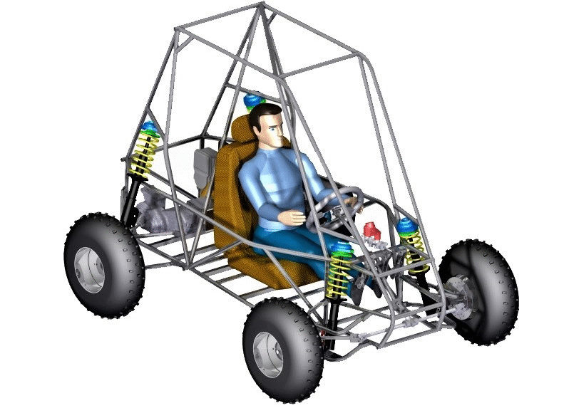
This project involved the design of upright/knuckle and it’s integration with the components of the wheel assembly namely – the A-arms (wishbones), hub, wheel rim, suspension struts, and brake calipers. The vehicle was an all-terrain style being built for a BAJA SAE 2016 competition (shown below) and had limited budgetary resources. The problem at hand was tackled using an unique design and manufacturing methodology. Looking back to 2016, I also provide fair criticism of the design and comment on possible improvements that could be made.
The Vehicle
Material Selection and Design
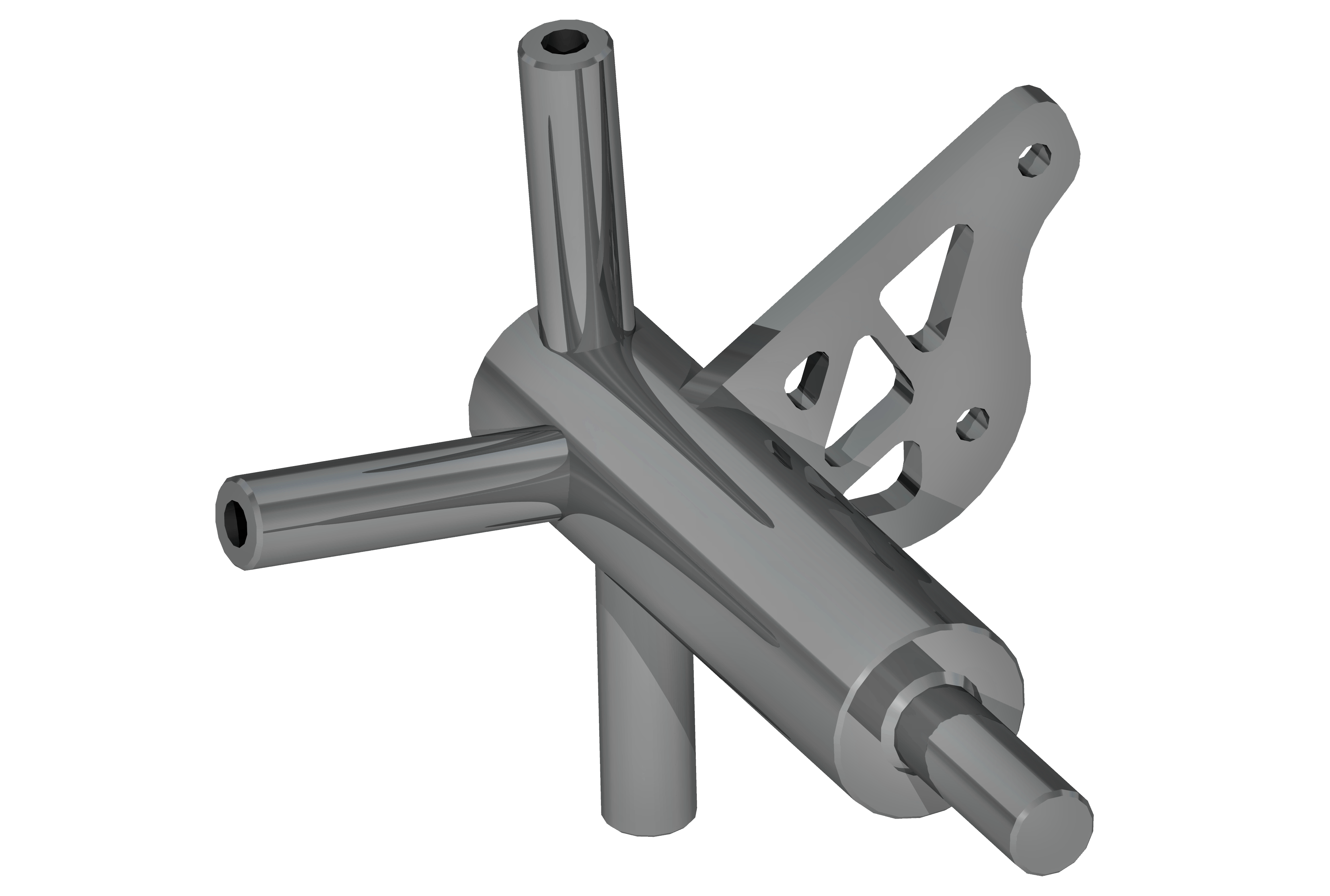
Primary drivers for material selection were cost and availability. Thus, Mild Steel conforming to AISI 1018 specification in the form of standard bar stock was chosen as against Aluminum. Since the 3-axis CNC we had in-house was down for maintenance during this particular period, I came up with a design that would require only the use of a CNC lathe for it’s primary structure (in addition to a laser cut brake pad mount) as is shown in the CAD model below. The protruding structures namely – the wishbone, steering link cylinder(s) and brake pad mount were slightly embedded in the main cylinder through machined pockets which provided additional strength over welds.
I enlist here a comparison between AISI 1018 Steel and Aluminum 6061-T6 to highlight some of the trade-offs that were consciously made. Favorable steel properties are bold.
| Property | Steel | Aluminum | Reference |
Cost  | ~ $9 | ~ $12 | [1] |
Density  | 7.87 | 2.70 | [2] | [3] |
Elastic Modulus  | 200 | 69 | [2] | [3] |
| Poisson’s Ratio | 0.29 | 0.33 | [2] | [3] |
Tensile Ultimate Strength  | 440 | 310 | [2] | [3] |
| Tensile Yield Strength | 370 | 276 | [2] | [3] |
Strength to Weight Ratio  | 55.90 | 114.81 | – |
Hardness  | 71 | 60 | [2] | [3] |
Fracture Toughness – Generalized Plane Strain  | Low Carbon Steels 41 – 82 | Aluminum Alloys 22 – 35 | [4] |
| Endurance Strength | 180 – 270 | 96.5 | [5] | [2] |
Thermal Conductivity  | 51.9 | 167 | [2] | [3] |
Coefficient of Thermal Expansion – Typical  | 12 | 23.6 | [5] | [3] |
| Machinability – Cutting compared to B1112 steel | 0.70 | 1.90 | [2] | [6] |
The design was analyzed and optimized using a finite element analysis software package (ABAQUS) employing a linear static – general type implicit solver. The primary boundary conditions were 1. Application of forces [1g, 2g, 3g] × 0.25 × Gross Vehicle Weight in x, y and z standard vehicle direction respectively at the bearing patch. 2. Application of force corresponding to the braking torque on the brake pad mount. and 3. Fixing the upper, lower wishbone mounting points and the steering link. i.e. x, y and z displacements to be zero. Here I was mindful of the fact that the upright being connected to a deformable shock absorber will experience considerably less force in z-direction under normal operations. However, care was taken to consider an extreme case when the vehicle lands on one tire resulting in a full strut compression.

The design was iteratively modified based on the different combined loading combinations that were studied. The following table lists some of the simulation parameters and results obtained.
| Solver | Static, General |
| Solution Method | Direct |
| Element Type | C3D10: 10 Node Quadratic Tetrahedron |
| Global Size | 4 [Finer as required on certain geometry] |
| Maximum Von Mises Stress | 160.9 |
| Factor of Safety | 2.3 |
Maximum Displacement – Magnitude  | 0.088 |
Manufacturing
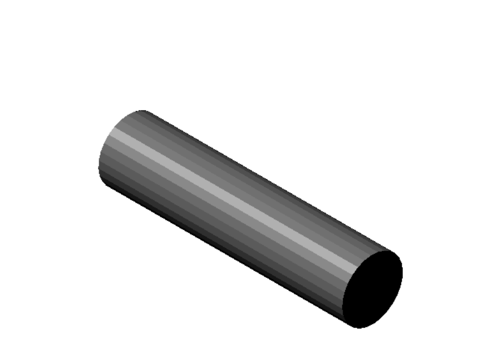
As mentioned above, the primary manufacturing technique for the cylindrical sections of the uprights was use of a CNC lathe. Tool path simulations were conducted for different components prior to actual machining, an example of which is shown below. The brake mount bracket was laser cut and all components were welded to the main cylindrical section using Tungsten Inert Gas (TIG) welding employing a suitable filler.
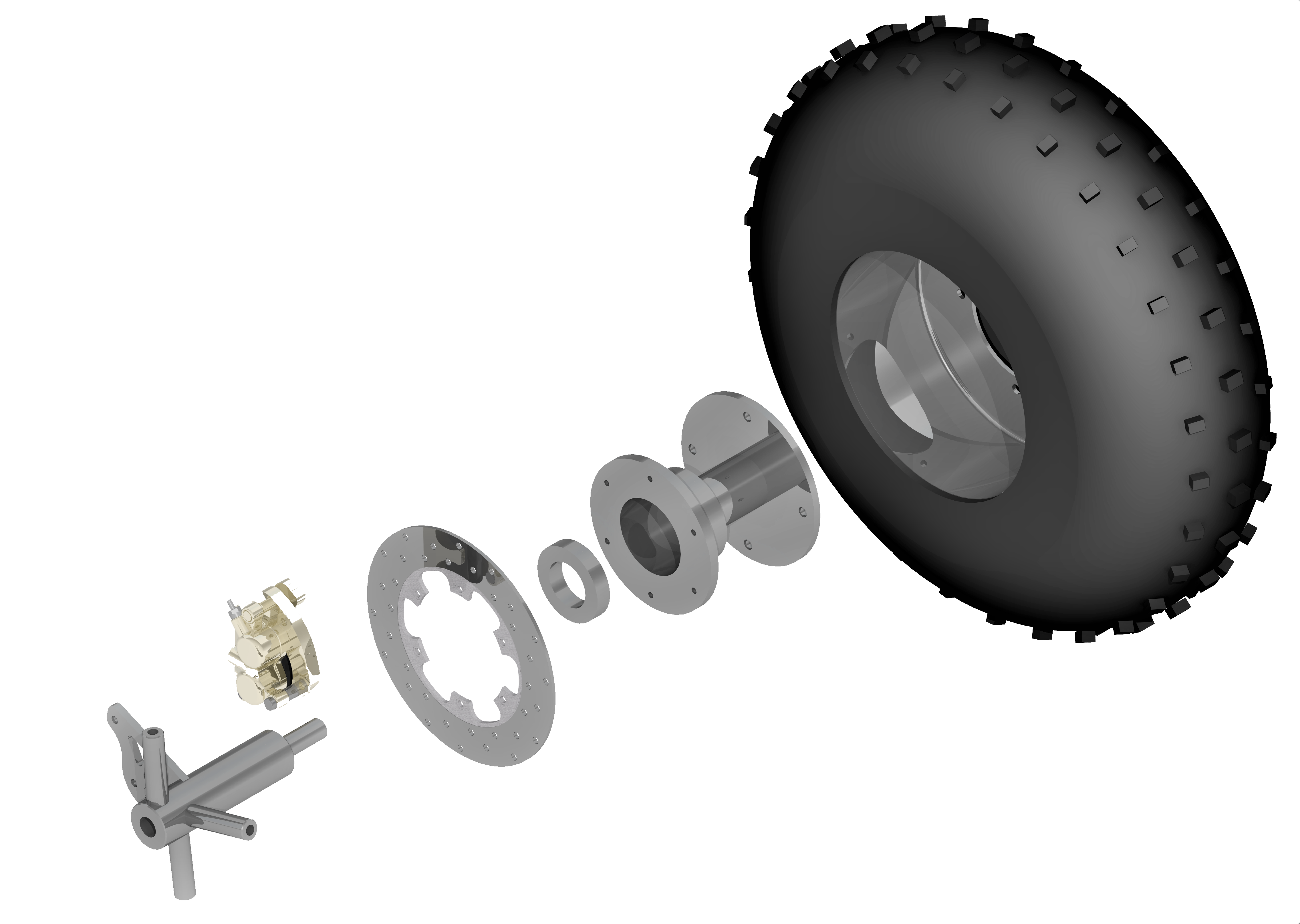
Wheel Assembly
The below figure shows the front wheel assembly of the vehicle consisting of the knuckle, brake caliper, disc/rotor, bearing, hub, rim, and tire. The following consideration were made taken with respect to the interference fits [7].
- Interference is reduced by radially acting loads.
- Interference is reduced when the bearing gets heated in operation and there is exists a temperature gradient along with material dissimilarities.
- The upper limit value on interference should not exceed 1/1000 of the shaft/bore diameter.
The fit between the bearing inner race and the knuckle shaft (ϕ 45 mm) was determined to be H7js6 [js6: 20 µm interference (T) to 8 µm clearance (L)] and that between the bearing outer race (ϕ 75 mm) and hub was P6h6 [P6: 45 to 26 µm interference (T)].
Assembly torques were determined using the equation that relates clamp load to applied torque given as 


Possible Future Improvements
The uprights thrived throughout the competition and showed no signs of failure, however the following improvements can be made to further augment them.
- Due to higher strength to weight ratio, possibly switching to Aluminum can reduce the overall weight of the part. However, since Aluminum has a much higher coefficient of thermal expansion and is softer, greater care would have to be taken in the interference fits.
- The factor of safety of the current design can be brought down from 2.3 to ~1.5 – 1.7 by shape optimization adding to the overall weight reduction.
- The current design although efficient in manufacturing, possesses several contours with high stress concentration. This can be detrimental in long service life conditions. Also, many stress concentration zones overlap with possible heat affected zones for welds which increases the risk/probability of possible failure. A uni-body can address these concerns; with an added cost of course.
References
[1] Midwest Steel and Aluminum. Online: https://www.midweststeelsupply.com/store/. Accessed: April 18, 2019.
[2] ASM Aerospace Specification Metals Inc. AISI 1018 Steel, cold drawn. Online: http://www.matweb.com/search/datasheet_print.aspx?matguid=3a9cc570fbb24d119f08db22a53e2421. Accessed: April 18, 2019.
[3] ASM Aerospace Specification Metals Inc. Aluminum 6061-T6, 6061-T651. Online: http://http://asm.matweb.com/search/SpecificMaterial.asp?bassnum=ma6061t6. Accessed: April 18, 2019.
[4] Materials Data Book, Cambridge University Engineering Department, 2003. Online: http://www-mdp.eng.cam.ac.uk/web/library/enginfo/cueddatabooks/materials.pdf. Accessed: April 18, 2019.
[5] MakeItFrom.com. SAE-AISI 1018 (G10180) Carbon Steel. Online: https://www.makeitfrom.com/material-properties/SAE-AISI-1018-G10180-Carbon-Steel. Accessed: April 18, 2019.
[6] Quaker. Machineability Ratings. Online: https://pl.quakerchem.com/wp-content/uploads/pdf/skill_builders/no10_machineability_ratings.pdf. Accessed: April 18, 2019.
[7] Bearing Fits. NTN Global. Online: https://www.ntnglobal.com/en/products/catalog/pdf/2202E_a07.pdf. Accessed: April 18, 2019.
