Introduction
The hardness test is one of the most commonly performed characterization technique on engineering materials as it describes the ability of the material to resist deformation. Before we use the word any more let us define Hardness of a material as i. Its resistance to permanent indentation and/or ii. The resistance of a material to scratching or wear [1]. It is also worthwhile to mention here that the hardness is not a fundamental property of a material unlike say the elastic modulus (when applicable). This is so because resistance to indentation depends on the shape of the indenter and the load applied. Let us now look at different hardness measurement techniques that are available which can be broadly classified into i. Macro ii. Micro and iii. Nano regimes. Nano scale hardness is covered in greater detail being an area of the author’s research.
Macroscopic Hardness
Brinell Hardness Number
In the Brinell test a steel or tungsten carbide ball 10 mm in diameter is pressed against a flat material surface under investigation with a load of either 500, 1500 or 3000 kg for a duration of 30 to 60 seconds. The diameter of indentation is measured by means of an optical microscope post indentation. The Brinell hardness number abbreviated as HB or BHN is defined as the ratio of applied load F to the curved area or actual area of indentation and is given by the equation below.

where D is the diameter of the ball, d is the diameter of the impression, t is the penetration depth is consistent units. It should be noted that annealed and work hardened materials have different indentation geometries and due care must be taken in the measurement of indentation diameter d. The indenter has a finite elastic modulus, it undergoes some elastic deformation under the applied load, which may lead to a finite inaccuracy in hardness measurement. A common strategy to minimize this inaccuracy is to use tungsten carbide balls, which due to its high modulus of elasticity deform less than steel balls.
The Brinell hardness number may be favored by engineer due to existence of empirical relationships between it and the ultimate tensile strength (Su), endurance strength (Se) of the material (in this case for steel) as is shown below [2]


Meyer Hardness Number
The Meyer hardness number abbreviated as MHN is based on the same indentation test as the Brinell test, the only difference being that the indentation load F is divided by the projected area of the indentation.

where Pm is the mean contact pressure.
Rockwell Hardness Number
The Rockwell test uses permanent increase in the depth of indentation as a metric to measure hardness. In this test, the indenter is pressed on the surface, first with a minor load (98.1 N) and then with an additional load of increased magnitude within 2-8 seconds. The difference in the depth of penetration (t) upon removal of the additional load is a measure of the hardness. There are several different types of Rockwell hardness scales that employ different indenter geometries, material and loads. Some of the most commonly used scales are listed in the table below.
| Scale | Indenter | Load (kg) | Formula |
| HRA | Diamond cone | 60 |  |
| HRC | Diamond cone | 150 | |
| HRD | Diamond cone | 100 | |
| HRB | 1/16 in diameter steel ball | 100 |  |
| HRF | 1/16 in diameter steel ball | 60 | |
| HRG | 1/16 in diameter steel ball | 150 | |
| HRE | 1/8 in diameter steel ball | 100 | |
Table: Rockwell hardness test particulars
The HRB and HRC are the most widely used scales which use a steel ball and a conical indenter respectively.
Shore/Durometer Hardness
The test is used to quantify hardness of materials such as thermoplastic elastomers, vulcanized (thermoset) rubber, elastomeric materials, cellular materials, gel-like materials, and similar soft and elastic materials (including skin). The test is usually done with the help of an instrument called a durometer. An indenter is first pressed against the surface and then a constant load is applied rapidly. The depth of penetration is measured after a set duration. The hardness is inversely related to the penetration and is dependent on the elastic modulus and viscoelastic behavior of the material. The geometry of indenter and force applied affect the measurement and no simple relationship exists between different durometer scales namely A, B, C, D, DO, E, M, O, OO, OOO, OOO-S and R. According to ASTM D2240 – 15, readings may be reported in the form M/60/1 where M is the type of durometer, 60 is the reading and 1 is the contact time.
Microscopic Hardness
Knoop Hardness Number
The Knoop test was uses a rhombic-based pyramidal diamond indenter in the shape of an elongated pyramid with opposite faces at angle of 172.50° and 130° . The loads range from 10 g to 5 kg. The Knoop hardness number (HK) is given by the formula.

where d is the length of the major axis or longest diagonal of the diamond shaped indent. The size of the indentation is generally in the range of 0.01 to 0.10 mm. This invites the need of careful surface preparation. The Knoop test is a micro-hardness test because of the light loads utilized and is therefore useful in hardness measurement of very small or thin specimens including those of brittle materials such as gemstones, carbides, and glass. It can be used to measure the hardness of individual grains in a metal.
Vickers Hardness Number
The Vickers test also formerly known as the diamond pyramidal hardness test uses as diamond indenter in the shape of a four-sided square-based pyramid. The angle between the opposite faces of the at the vertex is 136°. The loads (F) in this test range from 1 to 120 kg and Vickers hardness number (HV/VHN) is calculated with the help of the formula based on the actual area of the residual indent, as is shown below.

where d is the length of the mean pyramid diagonal measure after the removal of test force which is kept for 10 to 15 seconds. The Vickers test is applicable for testing a wide range of materials such as metals, polymers and ceramics.
Nano-hardness or Nano-indentation Hardness
Nano-hardness or Nano-scale hardness testing is widely applied on very small volumes of materials. In addition to hardness (H), it is also used to characterize mechanical properties such as elastic modulus (E), storage (E’) and loss modulus (E”), yield stress (

The advantage of nano-indentation is easy sample preparation and accurate analysis techniques based on the load displacement characteristics without actual measurement of indentation area; which are now integrated with power computer softwares. In this method an indenter of known geometry such as a cone, cube corner or three-sided pyramid (Berkovich tip) is used to penetrate the test specimen with use of a suitable load function. There is usually a holding period in the load function to consider the time dependent plastic deformation. Since both elastic and plastic deformation take place during the indentation and the elastic depth portion is almost fully recovered and it is important to pay careful attention in calculation of indentation area(s).
According to presently accepted method, the nano-indentation hardness (H) is consistently defined as the ratio of maximum indentation load (Pmax) to the contact area (Ac).

At this stage, it is worthwhile to discuss ways to estimate the contact area (Ac) accurately without the use of microscopy. In this respect, the work of Boussinesq, Hertz, Sneddon, Tabor, Stillwell, Doerner, Nix, Pharr and Oliver has been instrumental in determining Ac as a function of contact depth (hc). The figure below illustrates what we mean by hc.
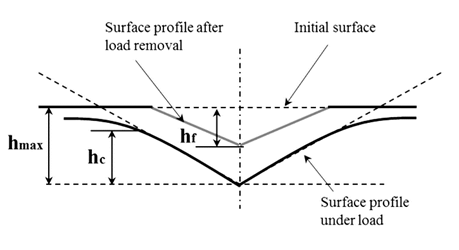
Figure: Schematic representation of an indentation section [3]
For an indentation tip such as say a perfect three-sided pyramid (Berkovich tip), knowing the half angle 65.27° and included angle 142.30° allows the contact area can be calculated (with the geometric considerations) in accordance to the equation below.

It should be however noted that a singularity point in any tip, if achieved, shall become blunt over time and assume the shape of a paraboloid after repeated indents. As a result, a modified area function with additional calibration coefficients (Cn) in the form of equation below is used to account for any error in contact area that may be arise.

The Sneddon’s equation can now be used to estimate the contact depth (hc) as follows:

where hmax is the maximum contact depth as is shown in figure above and 
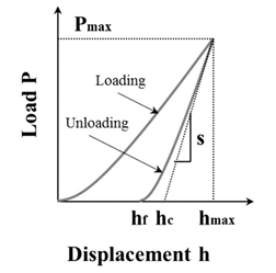
Figure: Schematic representation of an indentation load versus displacement [3]
It is also observed that the logarithmic counterpart of figure above shows linear representation and hence the unloading curve can be best described by a power law in the form of.

where A, m and hf are all determined by a least square fitting procedure on empirical data. The stiffness then can be calculated by differentiating above equation at maximum depth of penetration. With all required variables calculated as described, the hardness can be finally calculated. Also, the parameters at hand allow us to calculate the reduced modulus which is given by equation.

where is the geometric parameter with has value 1, 1.01 and 1.034 for circular axisymmetric, Vickers pyramid and Berkovich pyramid respectively. The reduced modulus can also be expresses in the from as shown in equation below, thus enabling us to determine sample elastic modulus (E) with knowledge of sample’s Poisson’s ratio (


For Berkovich diamond indenters common Ei and
References
[1] Kalpakjian, Serope and Schmid, Steve. Manufacturing Processes for Engineering Materials. Prentice Hall, New Jersey (2007).
[2] Bannantine, Julie., Comer, Jess and Handrock, James. “Stress-Life”. Fundamentals of Metal Fatigue Analysis. Prentice Hall, New Jersey (1990): pp. 1-39.
[2] Oliver, Warren and Pharr, George. “An improved technique for determining hardness and elastic modulus using load and displacement sensing indentation experiments” Journal of Materials Research Vol. 7 No. 6 (1992): pp. 1564-1583. DOI https://doi.org/10.1557/JMR.1992.1564.
[3] Yang, Zhou. “Thermo-mechanical Stability and Strengthening Mechanisms of Ti/Ni Multilayer Thin Films.” PhD Dissertation. University of Washington, Seattle, WA. 2016. URL http://hdl.handle.net/1773/35612.
[4] Oliver, Warren and Pharr, George. “Measurement of hardness and elastic modulus by instrumented indentation: Advances in understanding and refinements to methodology.” Journal of Materials Research Vol. 19 No. 1 (2004): pp. 3-20. DOI https://doi.org/10.1557/jmr.2004.19.1.3.
[5] Yovanovich, Michael. “Micro and Macro Hardness Measurements, Correlations, and Contact Models.” Proceedings of the 44th AIAA Aerospace Sciences Meeting and Exhibit AIAA 2006-979: pp. 1-28. Reno, Nevada, January 9-12, 2006.
[6] ASTM Standard D2240, 2010 (2015), “Standard Test Method for Rubber Property—Durometer Hardness,” ASTM International, West Conshohocken, PA, 2015, DOI10.1520/D2240-15, http://www.astm.org.
